¶ Extruder Assembly Guide
This guide is for extruder hardware kit that was shipped with the Positron v3.2.0 and v3.2.1 (Batch 1 and 2)
¶ Required Parts
¶ Hardware
Many of these parts will be in a bag labeled Extruder Kit
- Bearing, MF148ZZ
- Machine Screw, BHCS, M3x25
- M3x3 Set Screw
- Spider Shaft
- Primary Gear
- Bushing, POM, 8x4x11
- Idler Gear, Orbiter 2
- Shaft, 4x16
- Thumbscrew, M3x30
- Spring, 1x5.9x11.3mm
- Bearing, MR148ZZ
- ECAS04 Bowden Coupler
- Shim Washer, 3x6x0.5mm
- Heat set Insert, Brass, M3x6x5
- 3x Heat set Insert, Brass, M2.5x3x4
- 4x Machine Screw, BHCS, M2.5x18
- 2x Self-tapping Screw, M2x10
- Z Endstop Micro Switch and Cable
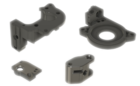
¶ Printed Parts
List of printed parts for the extruder assembly
- Extruder Main Body
- Extruder Motor Plate
- Extruder Bottom Plate
- Extruder Guidler
STL models can be found on the Positron Printed Parts Github
Models have not been scaled to account for material shrinkage
¶ Assemble
¶ Prepare the Printed Parts
Install heat set inserts into the printed parts
Parts Needed:
- 1x Heat set Insert, Brass, M3x6x5
- 3x Heat set Insert, Brass, M2.5x3x4
- Extruder Guidler
- Extruder Main Body
¶ Guilder
- Install the M3x6x5 heat set insert into the printed guidler.
¶ Extruder Main Body
Batch 1 Extruder Main Body did not use heat set insert but had screws that threaded directly into the printed part.
- Install all three M2.5x3x4 heat set inserts into the printed extruder main body.
¶ Motor Plate and Planetary Gear Shaft
For all the M2.5 screws, please use the included LDO screwdriver.
Parts Needed:
- 1x Bearing, MF148ZZ
- 1x M3x3 Set Screw
- 1x Spider Shaft
- 1x Primary Gear
- 1x Bearing, MR148ZZ
- Extruder Motor Plate
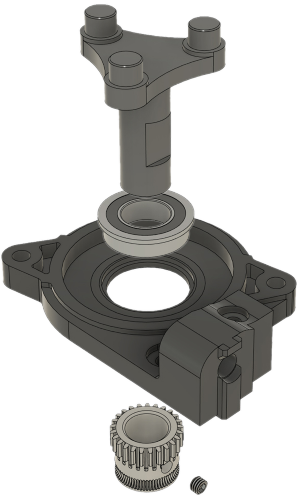
¶ Install CNC Shaft

- Place the MF148ZZ bearing into the hole of the Extruder Motor Plate and be sure it sits
flush or below the surface of the part.
- Insert the Spider Shaft through the opening of the MG148ZZ bearing.
¶ Install Primary Gear
- Slide the Primary Gear onto the Spider Shaft.
- Line up the hole in the Gear with the flat spot on the Spider Shaft.
- Screw in the Set Screw through the gear and stop right before it touches the flat spot.
- Now slide the gear all the way down the Spider Shaft until the Set Screw hits the end of the flat spot.
- Tightened down the Set Screw until the gear doesn't move, the height of the gear will be adjusted later.
- Place the MR148ZZ bearing on the end of the shaft and get ready for the next step.
¶ Install Lower Half
Parts Needed:
- 3x Machine Screw, BHCS, M2.5x18
- Assembled Extruder Motor Plate
- Extruder Main Body
- Extruder Bottom Plate
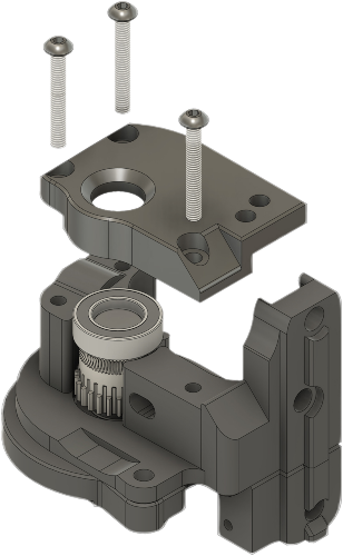
¶ Main Extruder Body
- Combine the Extruder Motor Plate and Extruder Main Body.
- Flip over for next step.
¶ Install Extruder Bottom Plate
- Cover the Extruder Main Body with the Extruder Bottom Plate and press it flat. If it does not
sit flat press the MR148ZZ bearing into the Extruder Bottom Plate first. - Secure Extruder Bottom Plate with three M2.5x18 BHCS Screws
Batch 1 uses three M2.5x10 BHCS Screws and only taps into printed part.
¶ Prepare the Extruder Guidler
Parts Needed:
- 1x Bushing, POM, 8x4x11
- 1x Idler Gear, Orbiter 2
- 1x Shaft, 4x16
- Extruder Guidler
- Place the bushing into Idler Gear.
- Rotate Extruder Guidler so larger opening is facing up.
- Position the Idler Gear (Gear teeth side down) into the opening of the Extruder Guidler and secure with the 4x16 Shaft (Smooth end first)
- The 4x16 Shaft has knurling on one end. Press fit the Shaft into the Extruder Guidler until it is flush and holds the Idler Gear in place.
¶ Check Filament Path
Parts Needed:
- Piece of filament longer than the extruder
- Assembled Extruder Body
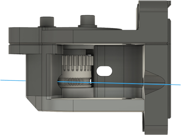
- First loosen the M3x3 Set Screw so the Primary Gear can slide up and down.
- Insert a piece of filament as shown in above photo.
- Align the Primary Gear so the filament teeth are centered on the filament and the exit path for filament, and tighten down the M3x3 Set Screw.
¶ Install the Extruder Guidler
Part Needed:
- 1x Machine Screw, BHCS, M3x25
- 1x Machine Screw, BHCS, M2.5x18
- Assembled Extruder Main Body
- Extruder Guidler
¶ Secure Guilder
- Position the Extruder Guidler with gear teeth side up and into the Extruder Main Body.
- Secure with a M3x25 BHCS Screw. The screw taps into the Extruder Bottom plate.
¶ Anchor Motor Plate
- Secure Extruder Motor Plate with a M2.5x18 BHCS Screw. Screw taps directly into the printed parts.
¶ Install the Bowden Coupler
Parts Needed:
- 1x ECAS04 Bowden Coupler
- Assembled Extruder Body
- Remove any rubber from the Bowden Coupler
- Install the Bowden Coupler into the extruder. The Bowden Coupler flange should be flush with the Extruder Body.
¶ Install the Thumbscrew
Parts Needed:
- 1x Thumbscrew, M3x30
- 1x Spring, 1x5.9x11.3mm
- 1x Shim Washer, 3x6x0.5mm
- Assembled Extruder Body
- While holding the Thumbscrew, drop the Spring onto the bolt end followed by the Shim Washer.
- Insert Thumbscrew from opposite side of the Guidler and thread into the Heat Set insert until Thumbscrew head is flush with the printed part above it.
¶ Install the Endstop
Parts Needed:
- 2x Self-tapping Screw, M2x10
- 1x Z Endstop Micro Switch and Cable
- Assembled Extruder Body
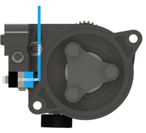
- Using the photo above prebend the wires on the Z Endstop with the lever facing down, in preparation to mount it.
- Secure the endstop to the printed part using two M2x10 Self-taping screws.
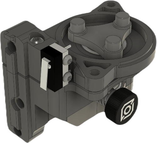
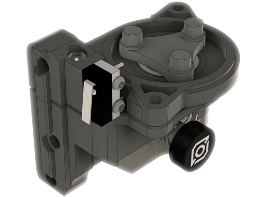
¶ Extruder Complete
- Congratulations the extruder is complete, the motor will be mounted towards the end of the Positron v3.2 assembly.